Description
| packing unit | 1 piece |
|---|---|
| weight | 38.0 kg |


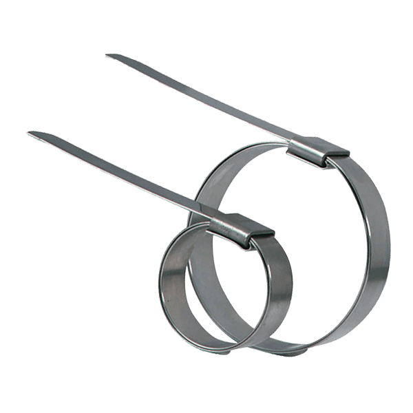
to apply Bandimex Preformed Clamps
| packing unit | 1 piece |
|---|---|
| weight | 38.0 kg |
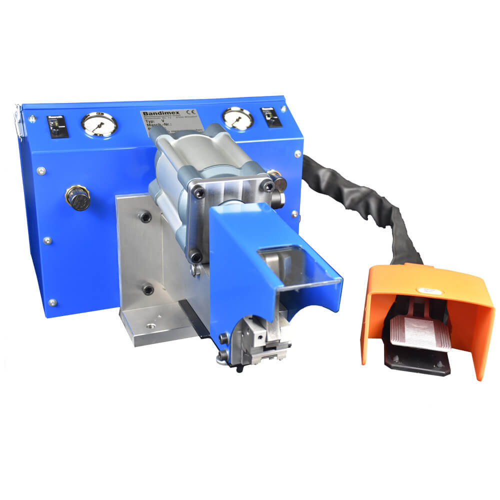
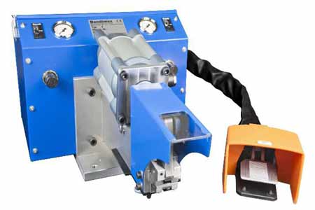 The BANDIMEX air tool is an air controlled, full automatic tensioning tool for applying BANDIMEX performed clamps. Operated by pedal – both hands are free to manipulate the object to be clamped.
The tool’s control panel allows optimal adjustment for various kinds and sizes of hoses.
An ideal tool to clamp hose, cables and ropes of various constructions with outer diameters of 10 to 200 mm.
Each clamp is pulled down with exactly the same preset pressure in seconds.
BANDIMEX performed clamps come in 21 diameters and combinations of 5 band width, a total of 38 various clamps are available. If this is not enough on request we can also manufacture additional combinations of diameters and widths.
Screw down base plate to the work bench in such a manner that the tensioning head has sufficient distance to the edge of the bench to allow easy and unobstructed mounting of clamps on all sizes hose.
The air inlet is a ⅜“ male thread with a mounted nipple suitable for quick connect coupling ID 7,2 mm. Pressure setting at the incorporated service unit should not be less than 101 psi (7 bar), and not more than 116 psi (8 bar), it is set according to these values, when tool leaves factory.
Fill vessel of oiler (service unit) with special oil for service units (e.g. Festo OFSW-32), adjust set screw of oiler to obtain minimum oil mist in air stream. Check the two cutter blade screws for tightness once in a while. The footpedal may be screwed to the floor.
On the tables and pressure gauges settings are shown in ‚bar‘ and ‚psi‘. For exact adjusting ‚psi‘-settings should be employed.
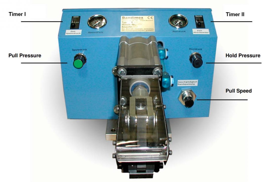
Step on pedal – piston is pulling in (keep the pedal down!) – turn knob and set pressure reading on the gauge to the pressure required (refer to schedule!)
- loosen counter nut on top of knob before turning, and fasten again after setting
This unit regulates the period of time between beginning of cycle (pressure build-up), and switching to hold pressure. The setting is very accurate and individually adjustable for each hose size. We recommend to take more time the larger the hoses are; so it’s possible to re-adjust the hose before cutting.
When the clamp is pulled down and piston stops at the set reading, the pressure should remain for 1 or 2 seconds to allow the clamp to settle.
Regulates the speed of piston.
Slower: Turn screw to the right
Attention: Don’t turn the screw past stop
Faster: Turn screw to the left
Press down pedal repeatedly while adjusting until requested speed is obtained.
In order to keep the clamp from losing tension during the cut-off operation, and to guarantee a secure locking of the buckle, a certain amount of pressure must be maintained in the cylinder.
This pressure varies according to width of band and the nature (composition) of the hose (refer to schedule), and is set in the same manner as described under 1., but after the timer has released the pull pressure.
This unit regulates the period of time between switching to hold pressure and automatically cut-off operation. The setting is very accurate and individually adjustable for each hose size. We recommend to take more time the larger the hoses are; so it’s possible to re-adjust the hose before cutting.
| Band width of clamp | Pull Pressure bar | Pull Pressure psi | Hold Pressure bar | Hold Pressure psi |
|---|---|---|---|---|
| 1⁄4″ | 0,6 | 9 | 0 - 0,35 | 0 - 5 |
| 3⁄8″ | 1,7 | 25 | 0 - 0,35 | 0 - 5 |
| 1⁄2″ | 2,5 | 37 | 0 - 0,35 | 0 - 5 |
| 5⁄8″ | 3,3 | 48 | 0 - 0,35 | 0 - 5 |
| 3⁄4″ | 4,1 | 60 | 0 - 0,35 | 0 - 5 |
For type 316 steel (CrNiMo) use 10% less, for Hi-C steel 30% less pull pressure.
The above values for pull and hold pressure are approximate.
They may vary according to the types of hose and couplings applied.
KEEP PEDAL DEPRESSED UNTIL CLAMP HAS BEEN CUT OFF!
You need to load content from reCAPTCHA to submit the form. Please note that doing so will share data with third-party providers.
More InformationYou are currently viewing a placeholder content from Turnstile. To access the actual content, click the button below. Please note that doing so will share data with third-party providers.
More InformationYou are currently viewing a placeholder content from Facebook. To access the actual content, click the button below. Please note that doing so will share data with third-party providers.
More InformationYou are currently viewing a placeholder content from Instagram. To access the actual content, click the button below. Please note that doing so will share data with third-party providers.
More InformationYou are currently viewing a placeholder content from X. To access the actual content, click the button below. Please note that doing so will share data with third-party providers.
More Information